

RGB for NES
Today there will be about refreshing and upgrading classic, 8-bit Nintendo Entertainment System (NES in short). It debuted in 1986 in Europe, in Japan it was much earlier in ’83 under Famicom name (short from Family Computer), and it looked quite differently:
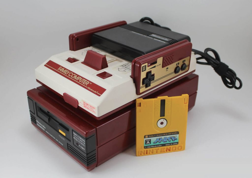
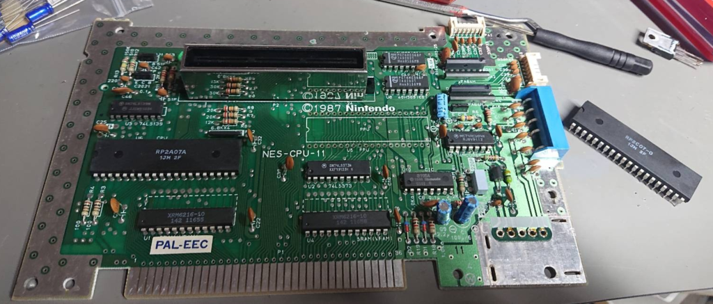
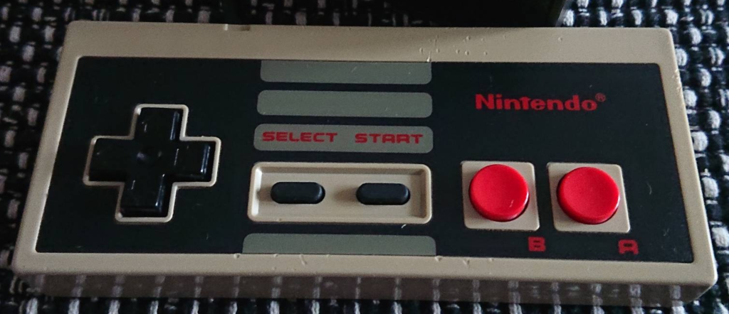
Unit I’ve got was used front loader, PAL version in good shape, although front cartridge lid mount on left side was cracked:

The plan was to:
- assemble NES RGB scart cable,
- clean up console interiors,
- exchange capacitors along with voltage regulator
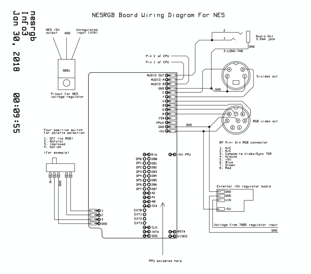
- install Tim Worthington’s NESRGB kit (v.4.1) with component video add-on board to get better video output than composite
I thought it will be easy work, console interior looks simple at first glance, but it took me around three days to properly install it, mostly because mix of lack of experience at dismantling NES (well, this is my very first one), scattered NESRGB instructions (I had to take some steps back and forth to push everything forward), laborous wiring and case modification work. There were also issues after closing the unit mostly related to cable management (we have to solder alot of wires).
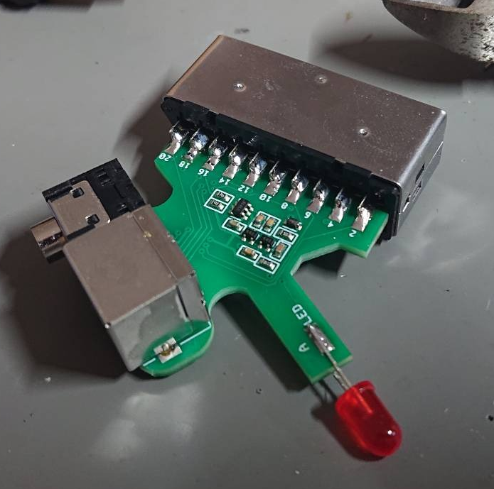
Scart cable kit
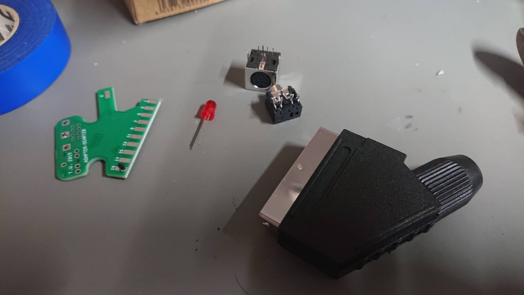
This was an easiest part there are simple assembly instructions, with kit I’ve got there is no need to glue cables with rubber tape, there is elastic plastic spring, which holds audio / video cables together, which is nice (.so there is no tape cutting). I think that making pcb with ports (rgb / audio) for this kind of cable was nice idea and for sure it will make it last much longer, broken cables could be exchanged if there will be something wrong with them.
Dismantling and case cleaning
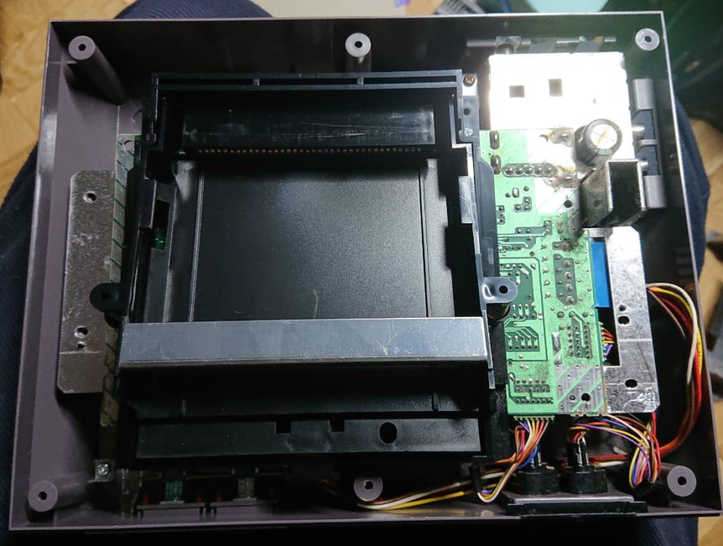
Whole unit had to be dismantled. Plastic parts went to bath in warm water with dish soap. Metal shielding, connectors were cleaned with isopropanol and contact cleaner.
Capacitors exchange
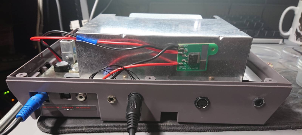
There wasn’t many capacitors to replace, but accessing those in power supply area was laborous.
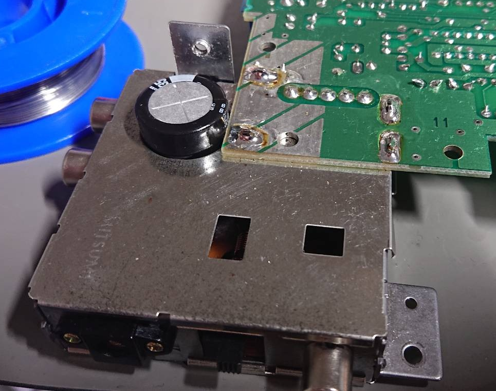
Power regulator had to be desoldered first along with metal box soldered directly to motherboard. Soldering points were quite big, so I had to remove all solder first with desoldering station. After that I applied heat to individual mounting points, put big, flat screwdriver between pcb and metal shiielding and I’ve tried to lift little by little whole power supply / composite video metal box until it fell off.
Second part getting an access to desoldered unit, which was another hassle. Before I’ve removed pcb I had to desolder three points underneath the board, desolder shielding, desolder three cinch sockets, unscrew and remove power supply socket. Without it pcb couldn’t be removed from shielding.
Shielding was cleaned with isopropanol, replaced four capacitors. After that everything had to be reassembled, resoldered and put in an original place. I didn’t solder power supply yet, because of further work on motherboard related to NESRGB.

Motherboard was cleaned with isopropanol, capacitors on main motherboard were also replaced with exact same values as marked on NES motherboard.
NESRGB installation
As a first step we need to remove PPU and don’t damage it. I suggest not doing it without proper equipment. I’ve had an accident, even with desoldering station I’ve managed to rip off half of the pad on one pin, when lifting PPU.
I’ve resoldered power supply part, replaced power regulator and glued it with fresh thermal glue, put PPU on socket to check everything is fine. It was fine, so I’ve moved to next, main part.
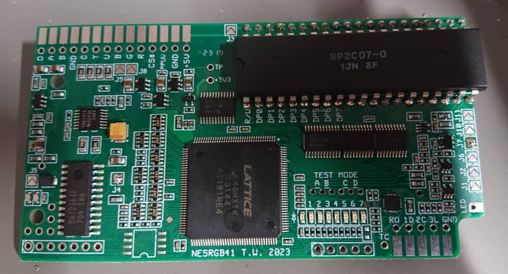
NESRGB board installation
At first gold pins supplied with NESRGB needed to be inserted into precision socket.
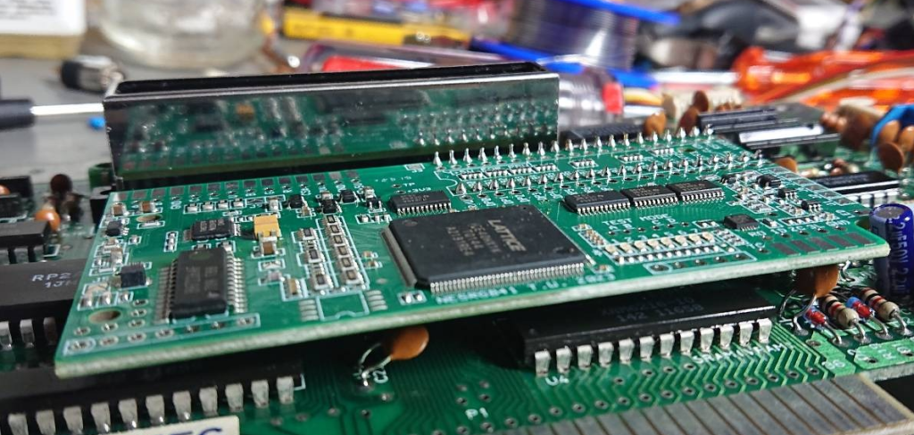
After that NESRGB board could be inserted, lying completely flat and pins 1 and 21 could be soldered to hold everything in place and make possible soldering other pins without fear of misaligning board or moving everything during the process. This will also guarantee that board will plug onto precision socket without issues later.
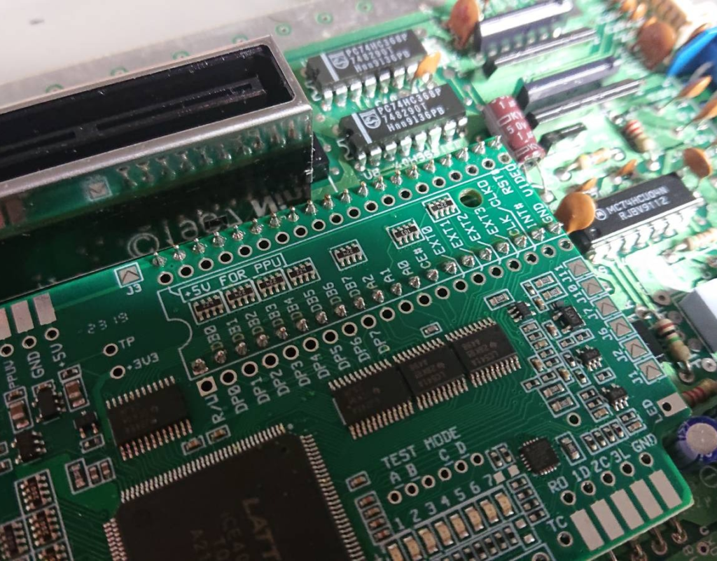
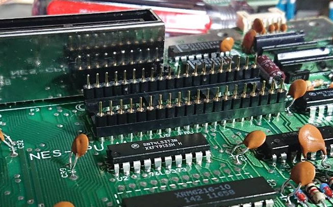
Lower row of pins needed to be trimmed down with side cutter, because it interfered with placing desoldered earlier PPU (which originally had trimmed down legs). Here is an angled view for you to make issue more visible:
Board needed to be removed first, because soldering was from bottom side. As earlier I’ve soldered 1st and 21nd pin to hold chip in place.
As we are installing NESRGB on PAL console several pads needed to be shorted (J4 and J7). After that I’ve plugged the board and tested system if it works using composite output. It worked, but turns out that when we are using composite output with NESRGB board enabled, then composite video output will be black and white. First time I thought that I’ve screwed installation, but it will look normal only when NESRGB is turned off by external switch or by pressing special button combination on pads. NESRGB pad control needed extra wiring, which I wasn’t ready yet, so I assumed that everything is fine.
Next I’ve soldered component video add-on board, but if you are doing the same I would suggest add long enough wire (long enough means wire, which will be long enough to reach pin 9 of an expansion port underneath NES motherboard) to J5 solder point for later, before installation. Otherwise later adding this wiring will be possible only from under NESRGB board (which means unplugging it, quite painful if you have alot of wires already soldered on).
So we have plugged NESRGB board, we need a break for a case preparation.
Case rework
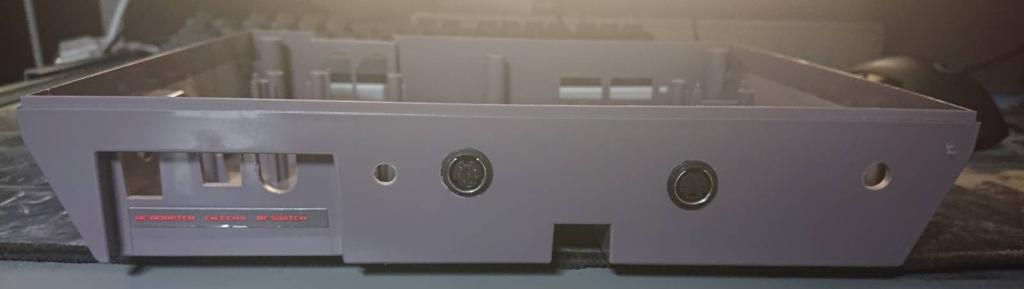
I’ve drilled four holes to mount minijack, rgb, s-video and component sockets. They turned not very aligned. Center was 2cm from upper edge of a case. I’ve drilled from the inside small hole with hand mini drill to b I’ve put proper drill to make sure that during drilling suspension poles of a case will not be damaged.
RGB and S-Video ports needed to be glued. I’ve tried to glue everything with two part epoxy glue, but it didn’t want to cure after advertised 3 minutes, so I had to remove it with white spirit (very greasy) / isopropanol and glued ports with more reliable hot glue gun.
After that I’ve soldered small S-VIDEO, RGB pcb’s from NESRGB kit.

Next I’ve prepared 9 (3 + 6) 25cm length kynar wires and soldered them to port pcb’s and secured boards with more hot glue between pcb and case.
NESRGB wiring
This is the job we need to do, most laborous one… Four position switch was skipped, because everything can be done from first pad after applying proper wiring and configuration of NESRGB board.
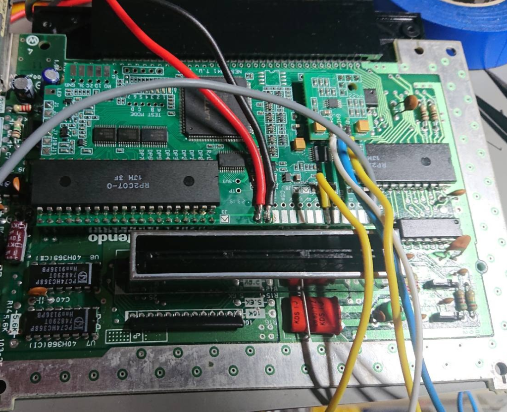
I’ve breaked installation in several parts. Firstly I’ve connected power supply. I’ve used thicker wires for GND and +5V between power supply unit, new power regulator and NESRGB board (I even have proper black and red colors for this purpose). I tinned all NESRGB solder pads, which I intended to use. Only CS# and PPUV were not touched. I’ve used 25cm long insulated wires for as suggested in installation manual.
After that I’ve connected component video add-on board to four pin socket. Component socket needs Y (yellow) signal directly from NESRGB board too, other three are from add-on board. I’ve soldered mini jack audio out socket too and used kynar wire to connect CPU pin 1 and 2 with Audio A / B on NESRGB board.
Afterwards I’ve tested if NES works with component video output. It worked, so I’ve proceeded to wiring S-VIDEO and RGB signals, which was basically soldering all the wires soldered during case modification to NESRGB board pads.

To have possibility of palette changes, turning on/off NESRGB, reset from NES pad, we need to connect some more signals from pad port, wire reset and short J1 pad (controller sets palette) and J6 (NES front loader positive reset polarity):

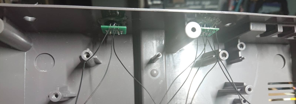
To use some extra audio capabilities wire from J5 of NESRGB board need to be connected properly to expansion port pins under the NES motherboard:
More about it can be read here. It’s useful with cartridges having expanded audio and Everdrive N8, which emulates expanded audio features.
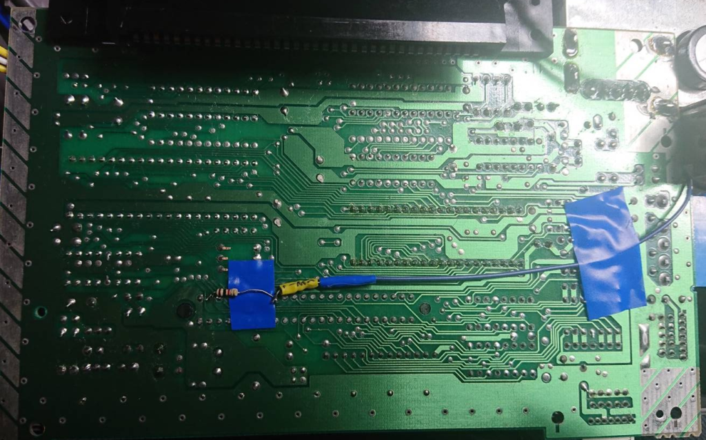
Two resistors are needed 1KOhm and 47kOhm resistors. 1kOhm is soldered between 2nd and 9th pin of an expansion port. 47kOhm one is soldered to 9th pin and our wire from J5. I’ve added shring tube around second resistor and secured some places with insulation tape to avoid shorts.
Iv’e made some cable management and grouped them with insulation tape. Afterwards lower shielding could be attached. Be extra careful at this stage to not damage previously soldered wires. During my take after I’ve reassembled the unit it didn’t turn on. So, I had to take some steps back, unscrew everything. Turned out that cartridge suspension part generated problems (was screwed too tight), when I’ve loosened the screws, console started to work, but after some tests I’ve lost blue color, which worked earlier.
Another dismantling revealed that during plays with lower shielding and rearrranging wires to get everything back into case, blue signal wire got damaged and broke in two after moving it.
Finally I’ve learned to check if unit works always after reassembling one part or a shielding at once. Before closing the case forever I’ve attached new power regulator to shielding. It has two sided adhesive tape under pcb.
Finishing
I’ve disassembled and cleaned dirty pads, interior with isopropanol, unfortunately rubber contacts are worn off, so probably they need to be completely replaced at some point.
I’ve added some labels to new ports (composite, should be component, corrected it later):
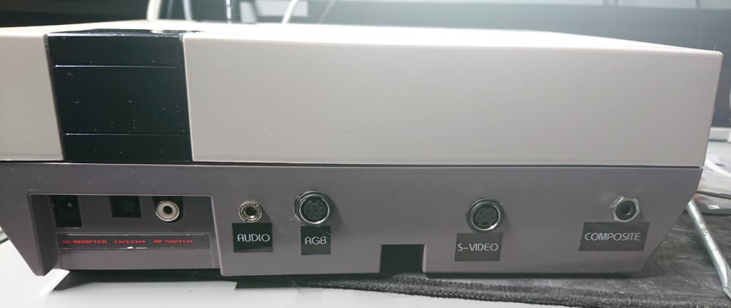
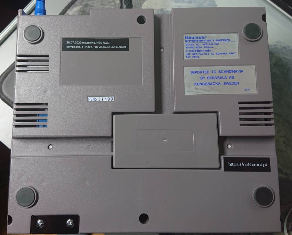
And left my markings for future generations (here too I’ve erronously printed composite instead of component video output):
End result
In short it was very tedious and most time consuming installation ever, but I think end result was worth it. NESRGB isn’t easy to install and I would not approach installing it without proper tools and skills. Boards are not cheap and have to be imported from Australia. Some shops from UK or EU sometimes got this board in their inventory though, but I guess prices there will have some portion of import fees too.
Besides video signal output improvements we can:
- Switch between six builtin palettes during runtime (START + SELECT + (LEFT / RIGHT)) or switch to 1st palette START+ SELECT+ RIGHT (held for 2 seconds)
- Perform reset (with START + SELECT + A +B combination), which is very useful with Everdrive N8. we don’t have to power cycle console, when we want access rom selection menu.
- Disable board completely if we would like to use default NES composite output (START + SELECT + LEFT held for 2 seconds ), without it there is no color.
- Use several video outputs at once, which is nice for recording or streaming.
One bad thing, which I’ve noticed is that on some (newer?) NES titles NESRGB needs some time to adjust (even on crt, when moving from one screen to another caused visible period, when nothing is displayed, just black), but I’m not sure why this happens. Maybe it is similar case with upscalers that they need to catch up after readjusting video signal (, which is quite common in games on older platforms). Other than that I’m very happy with an end result, although it was long and tedious way..
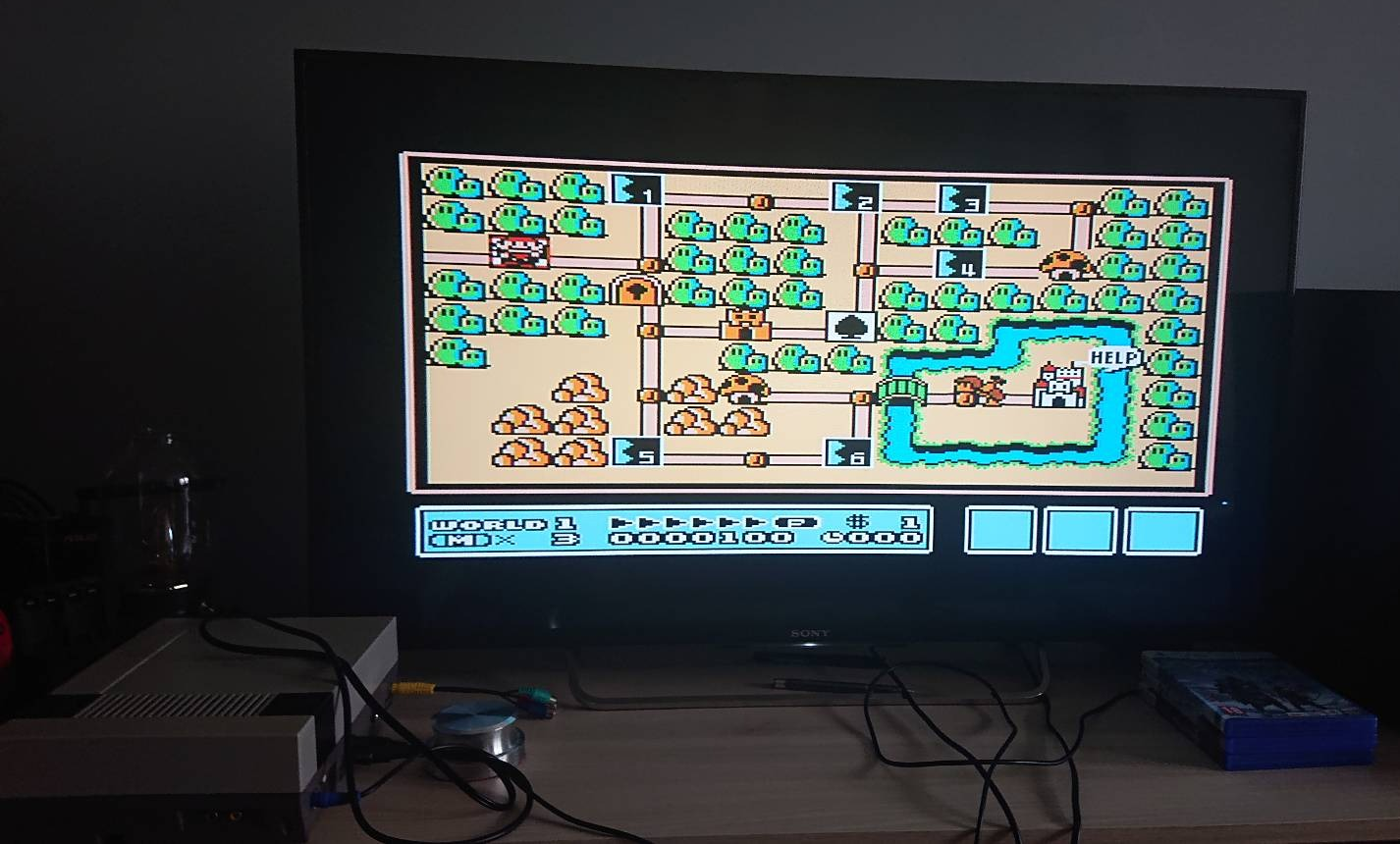
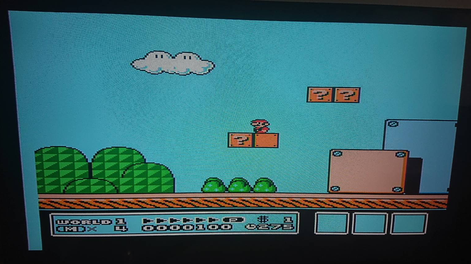
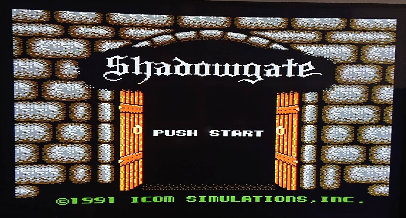
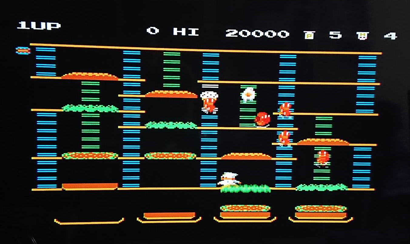
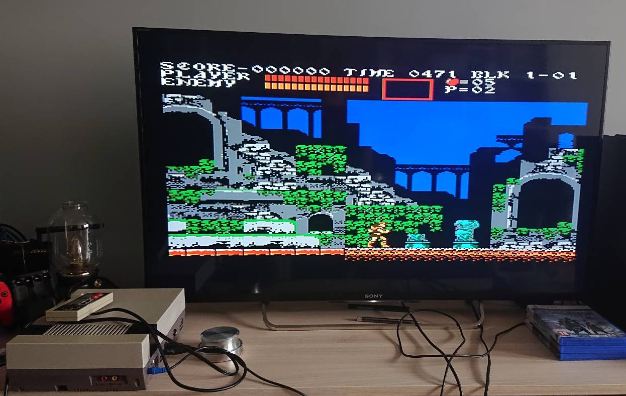
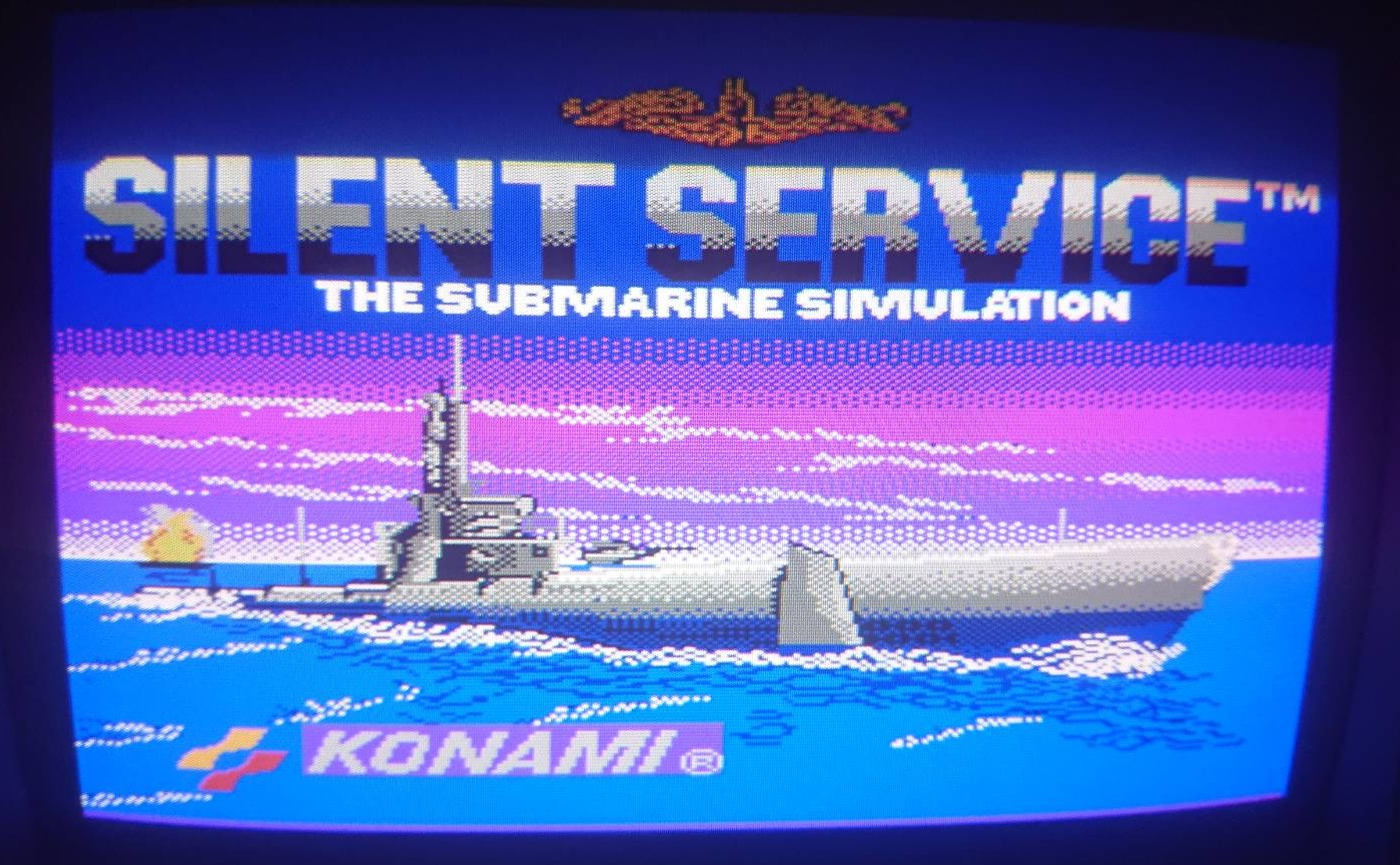
Here are some screenshots from crt and lcd.
O wpisie
Aktualnie czytasz “RGB for NES,” wpis w [nokturnal].
- Opublikowano:
- 27 July 2023 17:34 PM
- Kategoria:
- NES, Nintendo, Modyfikacje sprzętu, Wieści
Komentarze są zamknięte
Aktualnie komentarze nie są aktywne dla tego wpisu.