CT60/63 firmware upgrade with Xilinx Impact
Firmware upgrade is a scary thing a little, not proper operation can turn your machine into junk if not made properly. Sometimes upgrade is needed when manufacturer publishesh new version fixing detected bugs (like preventing using new add-on hardware like it was in EtherNAT and announced CTPCI), hardware working optimisations etc. Additionally it can happen that during upgrade with native tools something will go wrong (e.g. system crash during programming) which prevents booting of our machine. This can happen when upgrading ABE and SDR on the same machine with flash tool supplied in Didier Mequignon CT60 software pack. You will not be able to reuse your Falcon to fix it, because it will not boot at all. In this case you can send CT60/63 back to manufacturer, shoot yourself or fix it with PC, iMPACT application and JTAG cable. Below I will cover the third option. There also will be needed free LPT or USB port depending on what kind of JTAG cable you have.
Prerequisities
1) ISE WebPACK Software
iMPACT is a part of quite big (4,3gb, sic!) software package included in ISE WebPACK Software by XiLINX. You have to register on XiLINX website, download web installer, launch the installation and leave it for a half day or a day (depending on what internet connection speed you have). You can of course order it on DVD – the tools are free (we will not use these tools for developing ‘ missile, nuclear, chemical or biological weapons application’ so we can use them ;) ), but your credit card will be charged for shipping costs in this case.
This software package is available for:
- Microsoft Windows XP Professional (32-bit only)
- Microsoft Windows Vista Business (32-bit only)
- Red Hat Enterprise Linux WS 4 (32-bit only)
- Red Hat Enterprise Linux Desktop 5 (32-bit only)
- SUSE Linux Enterprise 10 (32-bit only)
In this tutorial I’ve used WinXP Professional 32-bit SP3 version.
2) JTAG cable
There are two kinds of them: LPT (RS232/DB25 connector) and USB ones. You can do them by yourself (schematics are freely available) or buy them. If you want to use cable both with PC and Falcon LPT version will be better option.
There is one important thing when programming ABE & SDR on Falcon with LPT cable (on the same machine where CT60/63 is plugged in), you have the modify the JTAG cable:
e.g. you have to disconnect the wire from #13 pin and reconnect it to the #10 pin on the DB25 connector side. You will also need too to reorganize the order of the wires on the JTAG connector side as on the schematics or pinout in the CT60 documentation.
For reorganising pins the Rena Electronics cable is most elegant one, because it has no connector at all, but loose cables with proper labels which you can connect as you want. This kind of cable I’ve used in this tutorial. It has also one nice feature – it has diode which indicates that the cable is powered on (it’s crucial thing when programming ct60/63 firmware).
When doing upgrade with PC no JTAG cable modifications are needed at all.
Preparation
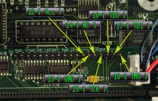
1) You have to connect JTAG to PC via LPT or USB port. I assume that the ct60 board is plugged onto F030 already and powered off. Firstly you can remove SDRAM module (it will be not needed during device programming and you will have better access to pins marked as “RESERVED” on CT60 board) and connect signals according to the diagram below:
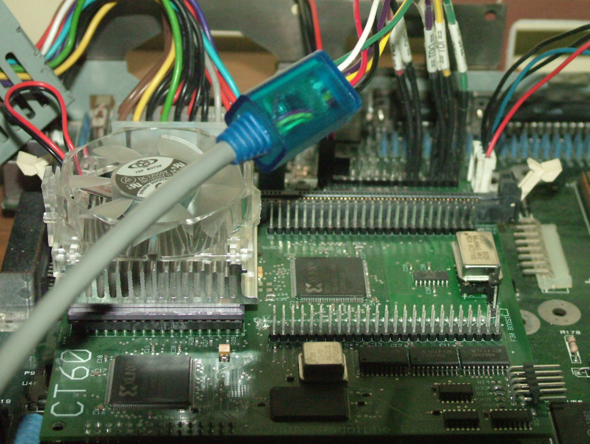
Here is the picture how it looked like on my setup:
Now download newest firmware from PowerPhenix site (ABE and SDR files), unpack them and put it in some convenient place on your hard disk.
Upgrade procedure description
Now you have to configure your cable set up in iMPACT (sometimes it is not needed and cable is automatically recognized). We launch iMPACT from Programs->Xilinx ISE Design Suite->ISE->Accessories->iMPACT. When “iMPACT project” pop-up window will appear. If you accidentally close this dialog, you can comback to it by choosing File->New->Impact project.
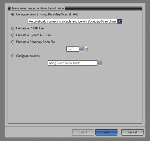
Now you have to select new project, and dialog will appear with option “Configure devices using boundary scan (JTAG)” (it has to be checked) and choose either “Automatically connect to the cable and identify boundary scan chain” or “Enter boundary chain manually”. Don’t click “Finish” button yet.
Now you have to TURN ON your Falcon and after a while click “Finish” button in dialog.
If you have correctly configured cable (like this was in my case) ABE and SDR chips will be automatically detected and you will be asked to select jedec files with firmware for them. iMPACT will go through each chip in chain and you have to assign correct file to them.
Firstly you have to select ABE*.JED and after that SDR*.JED (if you will do it in wrong order nothing will be working after the firmware update).
If there will be some problems with cable set up/connection the second option “Enter boundary chain manually” will let you configure cable and manual toolchain initialisation (be sure that Falcon is powered on).
You will have to right click on newly created and empty “Boundary scan window”, choose option “Configure cable” (set it to Parrarel III or Parrarel IV – both worked fine for me and LPT port to which they are connected OR set XiLINX USB cable in case USB JTAG cable). After that you can select “Initialise toolchain” option by clicking on “Boundary scan window” with right mouse button or simply by pressing CTRL-I. After that JTAG cable should be detected and you will be asked to choose *.JED files as I described above in automatic process.
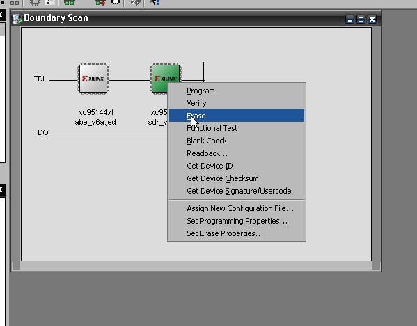
If everything worked fine you should se the screen as below:
Now for ABE and SDR you have to ERASE the old firmware, program them with new one and verify that they were flashed correctly.
1) Erase of old, existing firmware (by rightclicking on ABE and SDR chip icon and choosing ERASE option from context menu )
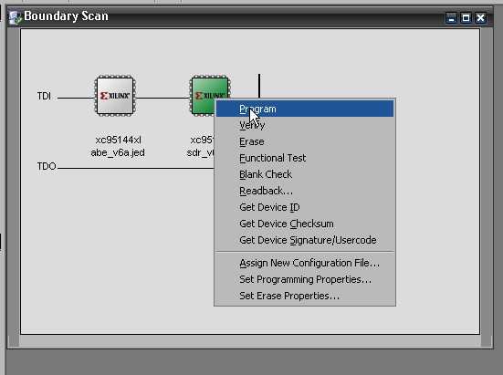
2) Program the new version (by rightclicking on ABE and SDR chip icon and choosing PROGRAM option from context menu – right files were already assigned in previous steps)
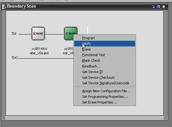
3) Verification of programmed chips (by rightclicking on ABE and SDR chip icon and choosing VERIFY option from context menu)
After each operation on each chip blue box will appear indicating that operation was successfull or red if error occured (in this case you can redo last operation or, if this will not help, check your cable set up).
Done!
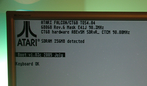
And that’s it. Place SDRAM module and launch the machine in 030 and 060 mode to check if everything works ok.
After the flashing with iMPACT you will notice that ABE and SDR versions aren’t correctly reported anymore. That’s because the flash memory region where these values are stored aren’t updated by iMPACT software. Only the native flash tool from native CT60 software package updates these values correctly. This the only issue that I’ve noticed when making upgrade.


